Miscellany... (updated 181224)
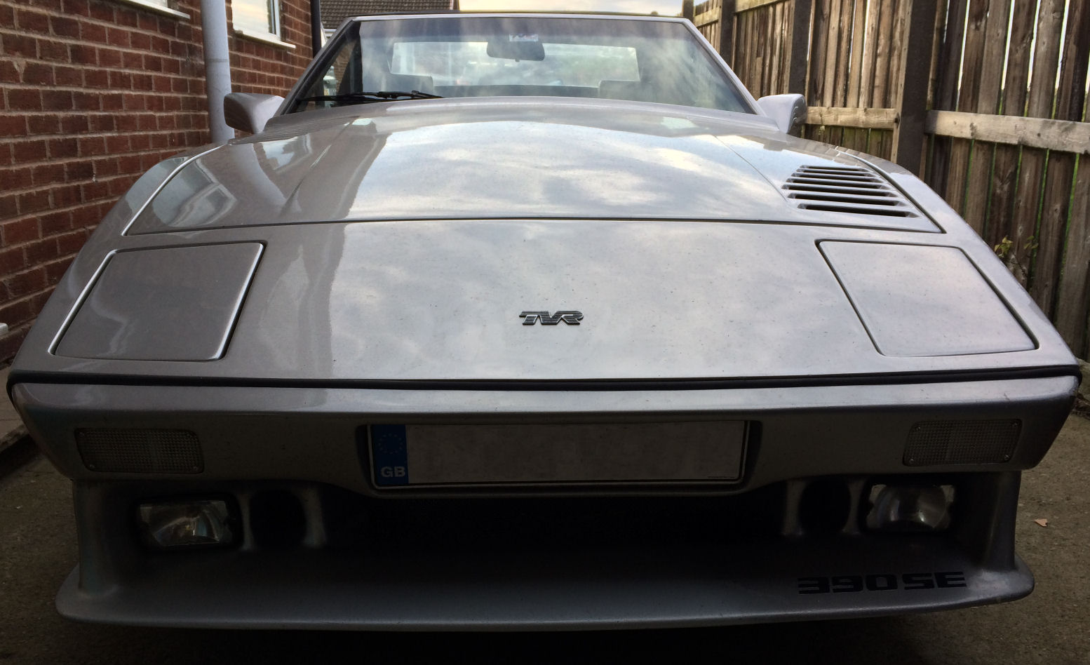
A few years back, on a drive-out with a selection of other sports cars, someone remarked that seeing the 390SE coming up behind was rather like watching a shark coming to get him! It's a fair analogy, judging by the above photo... :D
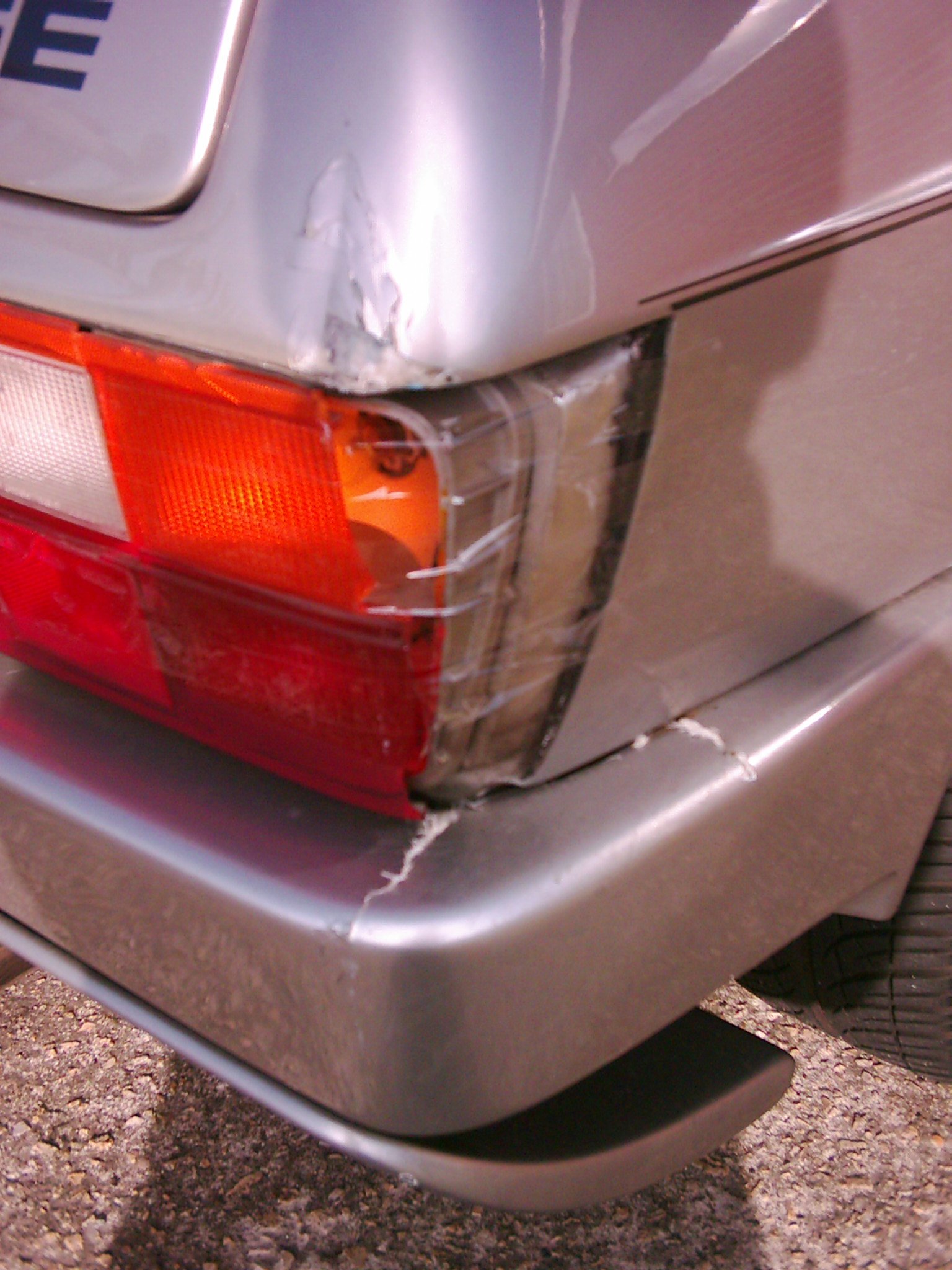
I reversed the TVR into one of those big fibreglass bins you find on garage forecourts. I wish I'd seen it before I'd reversed into it, but you know what those postage-stamp sized mirrors are like.
Anyway, the damage comprised one smashed rear lamp unit, a 'dent' in the rear wing corner, the rear bumper cracked in several places and some stress-cracking to the side of the offside rear wing. The good news is that the cracking was confined to the paint, there's nothing crunchy in the area and no evident broken fibres etc. on the inner surface of the wing.
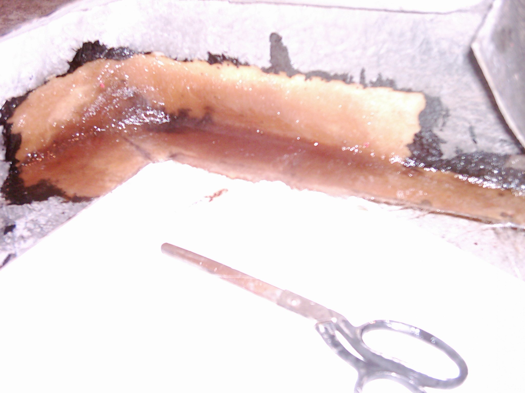
Even so, the bumper was going to need work. I unbolted it and cleared the workshop to allow me to make a mess! :O) It was immediately evident that the bumper mountings were shot. They're simple fabrications in mild steel, glassed-in to the bumper. Over the years the water had got in and the resultant laminations of rust had caused two swollen areas that were visible from behind the car, an effect which I've seen on a few wedges - it almost looks as though the bumper has had some lights removed and badly filled-in.
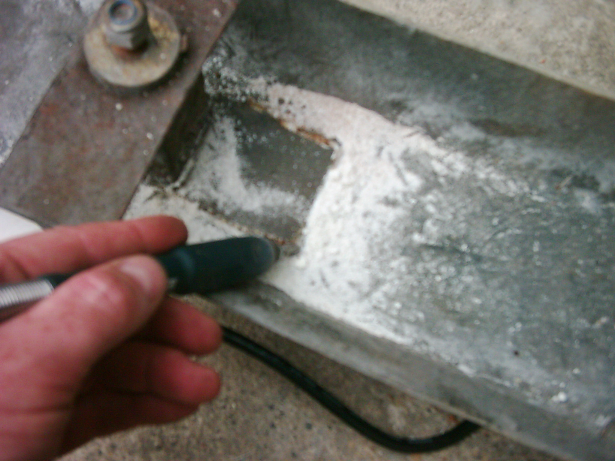
I wasn't about to spend time repairing the fractured GRP and put the bumper back on with knackered mountings so out came the Wizard (Black & Decker's answer to Dremel) and the old mounts were cut out.
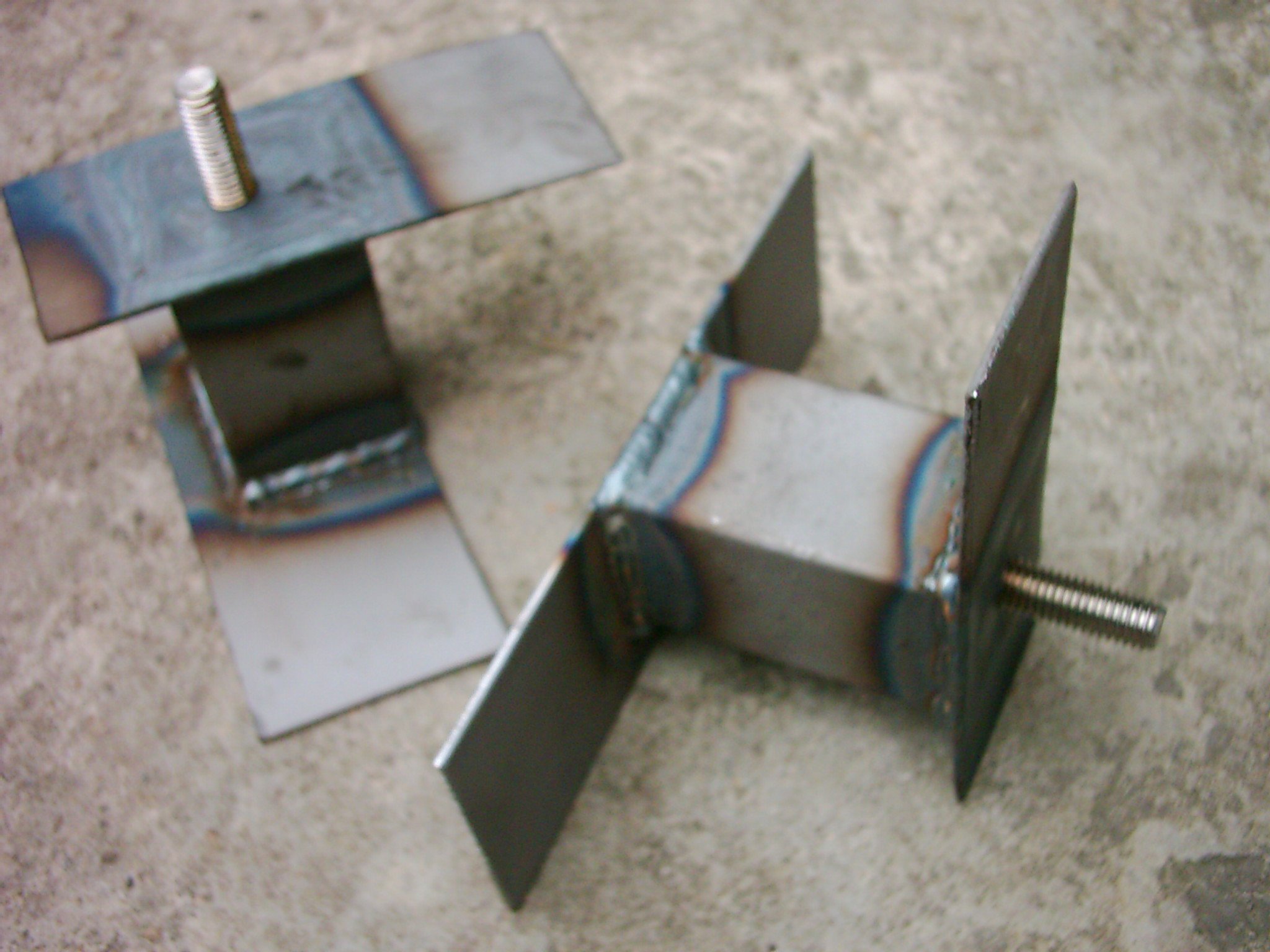
I estimated the dimensions and welded up some new mountings (using stainless steel bolts):
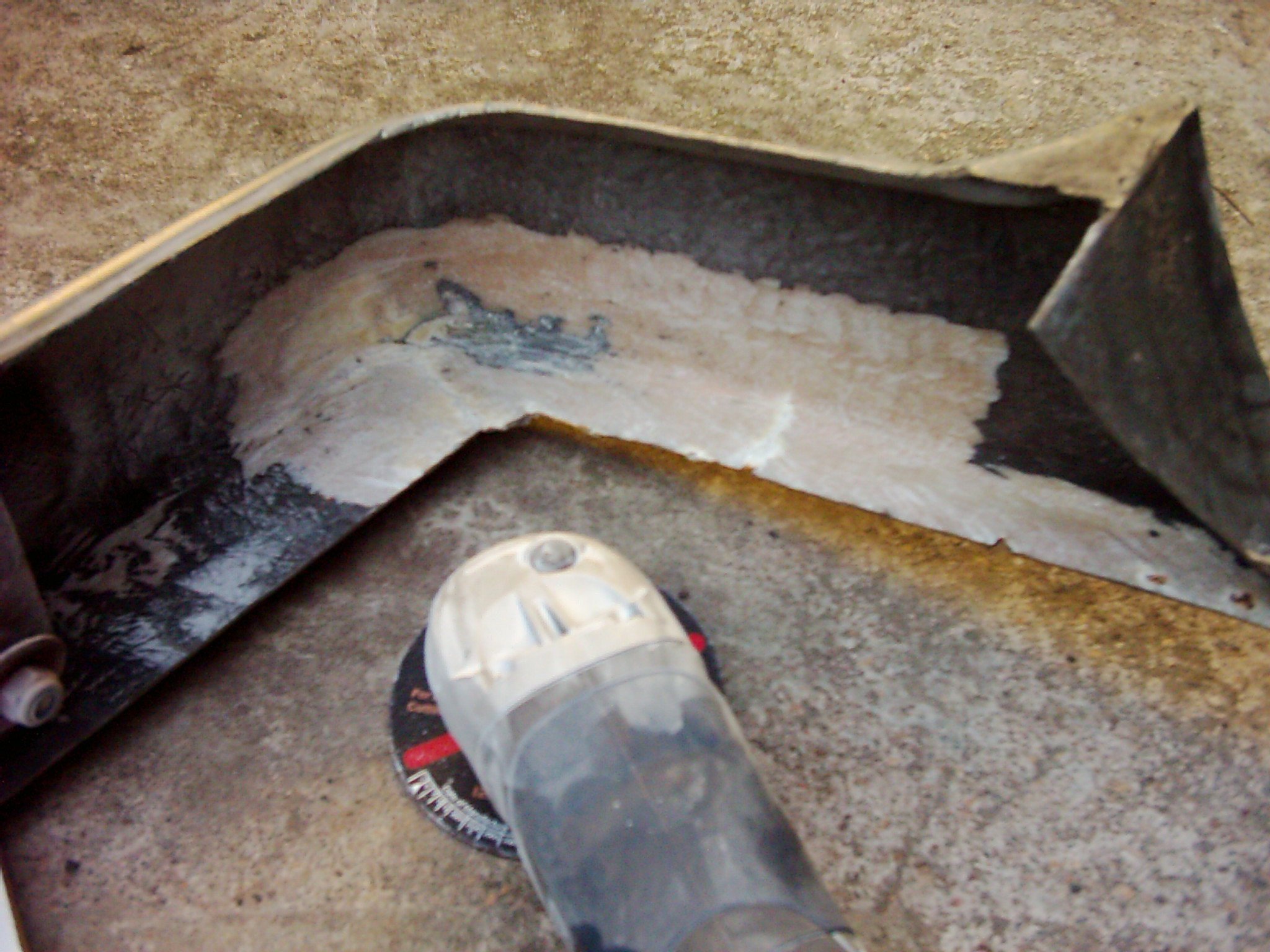
which were duly painted and glassed back in. I then ground the areas that would receive new reinforcement:
and liberally applied mat and resin to restore the bumper's shape and rigidity:
There wasn't much I could do about the swollen areas in the GRP where the old mounts had been rusting but I filled the cracks from the bin incident and repaired a few other odd holes where screws had been used to secure the bumper to the bottom edge of the wing (from inside the boot). I primed the bumper and filled a few more small defects that showed up in the primer. Then it was time for paint! And that was where the fun started. I knew the car had been resprayed at least a couple of times in its life and was no longer the 'factory' silver - I think I once saw it stated as 'aluminium silver'. The present colour has a much stronger metallic effect with black speckles and a hint of gold in certain lighting!
I paid a call to a mate of a mate who did custom paintjobs on bikes and he obligingly produced a swathe of colour chips from which we narrowed down a batch of three shades that looked pretty close. As luck would have it I'd called in at late afternoon on a bright day so almost every panel was lit slightly differently by the sun. There was only one chip that almost disappeared into the bodywork from any angle and we wrote down the code from it. I asked him what car it would have been from. You've got to be kidding, was his first response. His second response was to present me with a huge, telephone directory-sized book, cross-referencing colours to cars. The slight problem was that it only worked one way: it could tell me what colours had been used on a given car but it couldn't work in reverse. After all, if you take your car to a paintshop you know what the car is, you just need the colour match! The only way to do it was to work through the book, looking for any car that had used paint with the code from the chosen colour chip. I took the book home, made a brew and sat down. So, where to start. I could have begun at page 1 and worked my way through. Tedious! OK then, how about starting with the big names: Ford, Vauxhall, Mercedes, Rover, Fiat. That took an hour, no luck. Right: Nissan, Toyota, Renault, Volkswagen, Porsche. Another hour. Another brew. OK, let's rule out all the small-volume makers like Ferrari, Lotus, Lamborghini, Lancia... there it is! The Lancia Y10. Surely one of the most obscure cars in the UK and my TVR is wearing its paint. Fantastic... and, given the rarity of the 390SE itself, suitably appropriate.
Meanwhile, Glen the sprayer had ordered a litre of our selected colour and I duly collected it along with some thinners. I even blagged an old spraygun from him! It was time to clear the workshop again...
The Lancia colour proved to be a near-perfect match. With another lamp unit sourced via a helpful chap on an internet forum, the bulk of the damage remained on the rear wing. I wasn't too concerned about the stress cracks in the paint along the side but the 'egg-shelled' area just above the light needed something doing. The Wizard was employed again to chase out all the loose fragments and I laid-up mat and resin on the inside of the wing to maintain rigidity. As a temporary fix I merely filled the outside with a dollop of resin to prevent rain getting in and delaminating the GRP but one of these days I really must crack on and finish the repair...
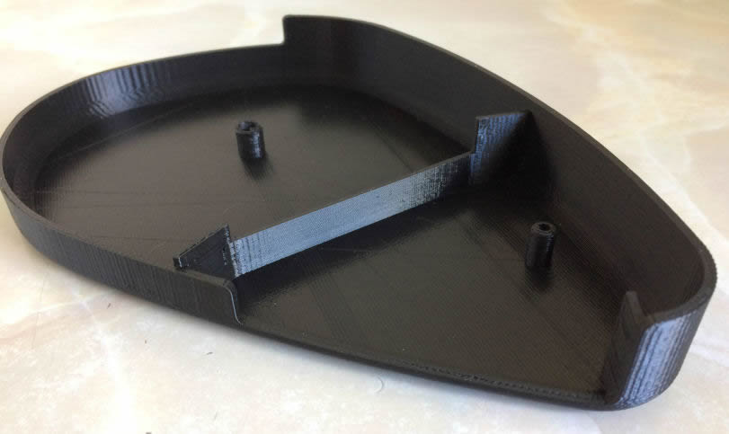
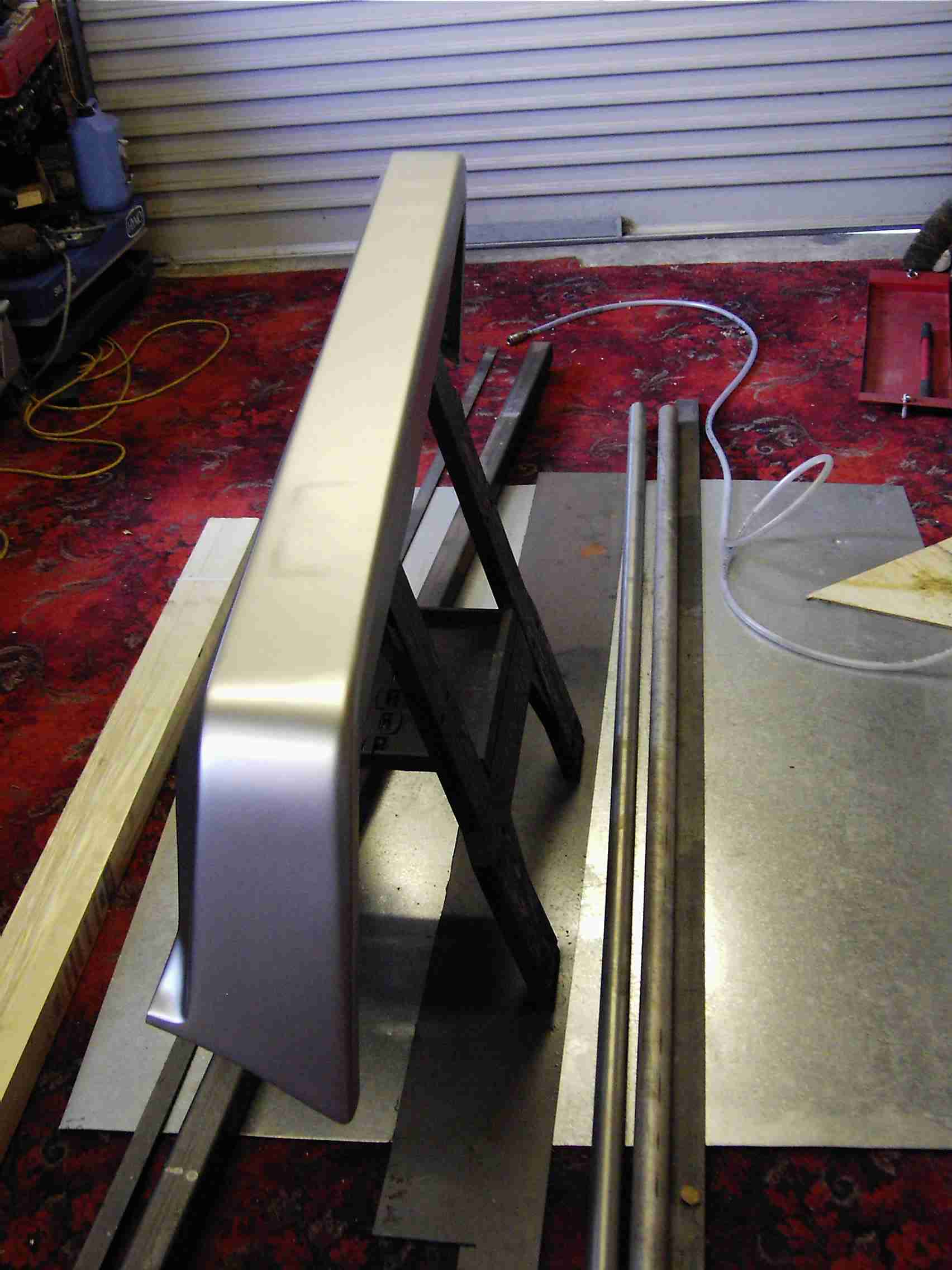
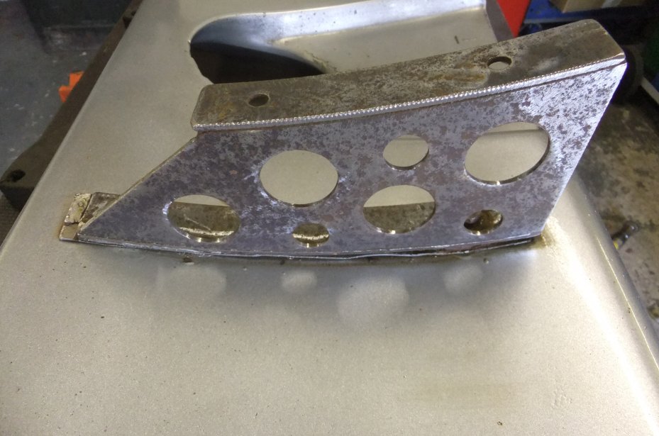
One of the most obvious distinguishing features of the TVR 390SE is the rear 'underwing' that hangs below the boot floor. Allegedly fitted to help high-speed stability, as on racing Jaguars of the period, its main purpose appears to be catching road muck and becoming stained by the exhaust gases! Whilst my major overhaul of the suspension and drivetrain was in progress in 2016 I decided to remove the underwing in order to have better access to the chassis tubes for cleaning and repainting. It also meant that I could de-rust and paint the wing's mounting brackets. I did try to remove the brackets from the wing with a view to sandblasting them, but the captive fixings crunched and splintered ominously so I opted to leave the brackets where they were and used a stripping disc on them instead... not as good but it'll do for now. This is the wing as seen from above (although you don't see this when it's on the car) - TVR clearly intended to use a dual-exit exhaust at some point...
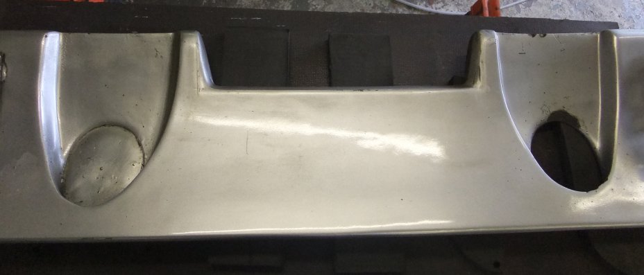
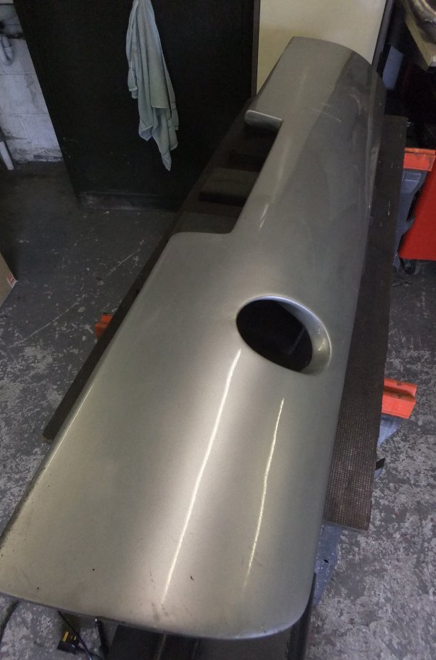
View of the lower surface; the cutaway area in the middle is to fit around the spare wheel well:
Just to show there was some serious aerodynamic intent, the aerofoil cross-section is clear here. Note that bracket fits where it touches!
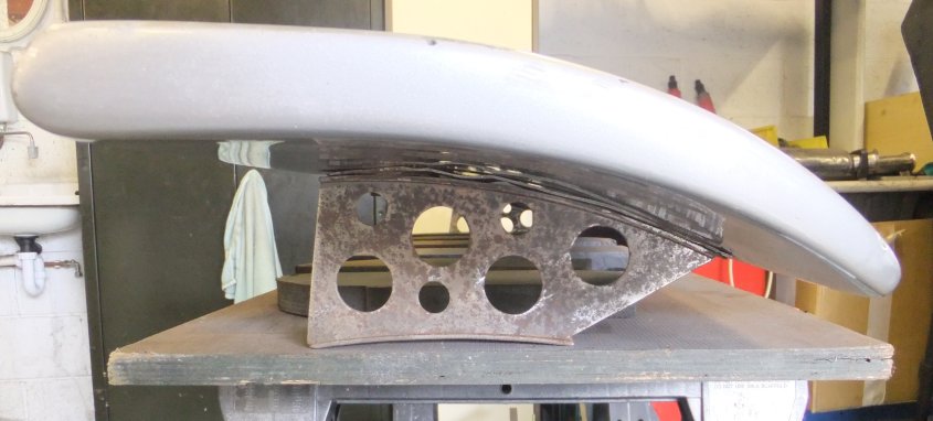
Mounting bracket is more elegant than you might expect (rust aside...); wing is made from GRP and weighs 9.7Kg.
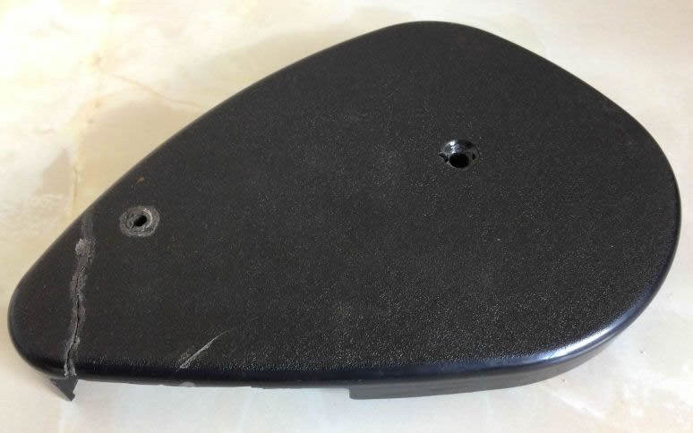
Seat Mechanism Cover
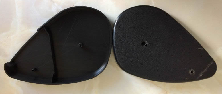
The seats fitted to the TVR Wedges were made by now-defunct Callow & Maddox Bros. of Coventry. Cambro, as they were known, also made seats for various other British car builders with the result that the TVR seats look as though they were lifted from another car. They weren't, but they do bear some similarities as Cambro used their standard range of parts to assemble them. The seat back recliner mechanism is mounted to the outer side of the seat and to hide the tension spring and associated parts a moulded plastic cover was fitted. It's not a very robust item and is easily broken, e.g. due to over-tightening the one screw that holds it in place (there's also a peg which pushes into an alignment hole). This cover on my driver's seat was cracked and the boss for the mounting screw was also hanging on by a thread...
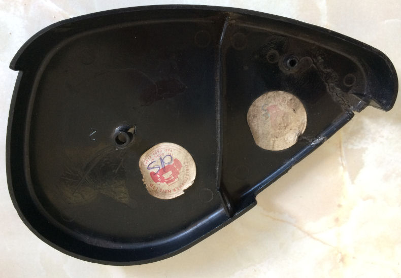
so I tried to find a replacement but failed (you can see this one has already been replaced as it has a sticker on from Christopher Neil sportscars). Then I thought, this would be an ideal candidate for the modern technology of '3D printing'! All I needed then was a 3D printer and a design for the part. And that's where the fun started. I reckon whoever drew that cover had just got a set of French curves for his birthday. There isn't a straight line on the bloody thing. So I experimented for a while until I had a passable outline of it in AutoCAD, then I extruded it to get the depth, added thickness to the wall, radiused the edges and put in various internal webs and a boss for the mounting screw... and emailed it to my son-in-law, who has a loft full of 3D printers :D Just to test proof of concept he rattled one off in 'draft' mode (which, just like an ink printer, gives reduced quality) and hey presto...
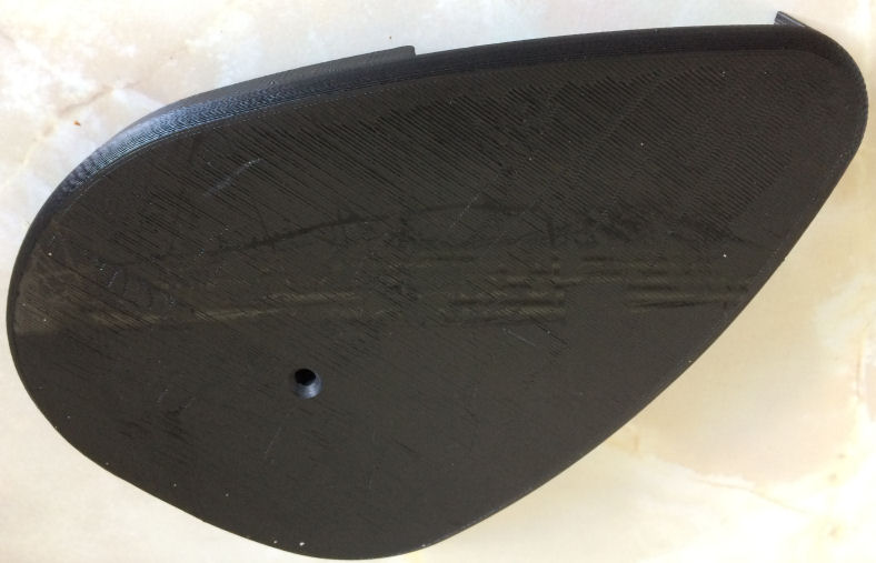
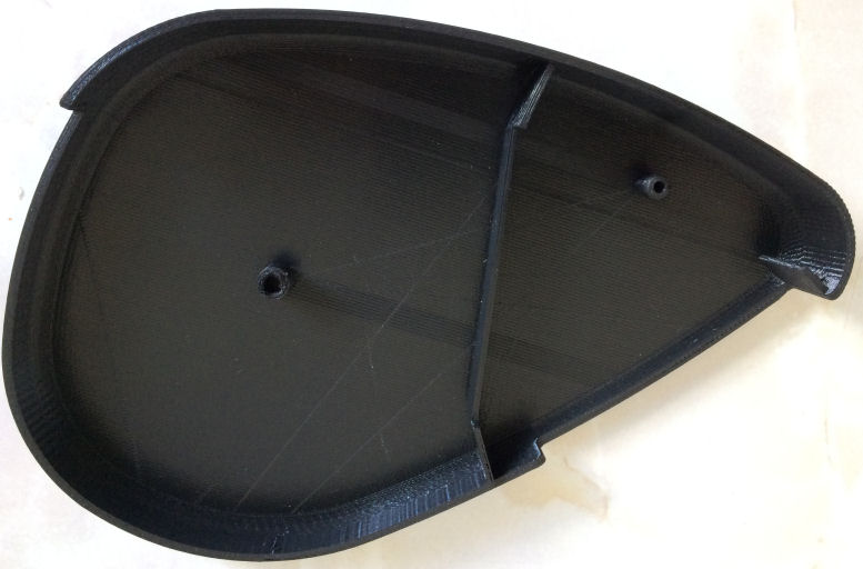
The major difference between this replica and the original is that the outer, flat face of the genuine article has a 'leatherette' texture where the copy is smooth (or it would be in full quality, this one has an all-over ribbed pattern from the extruding head). But the main thing is: it fits! If you compare the two there are tiny differences in some of the curves but hell, I effectively drew it freehand so it's not bad for a first go. My car doesn't have covers on the 'inboard' sides of the seats and I can't say I've ever noticed whether other cars had them either. At a guess they either weren't fitted as you can't see anything down that side of the seat anyway, or else they broke years ago and were never replaced. Once I have a finalised CAD drawing, of course, I can tell the software to 'mirror' it and produce an exact, opposite-handed version as well... though it might benefit from having the slot filled-in (where the tilt release handle exits on the outboard version). Another job for another day :) (EDIT: done it!)
Back to back (replica is on the left):
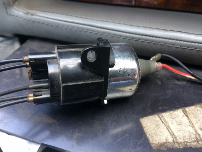
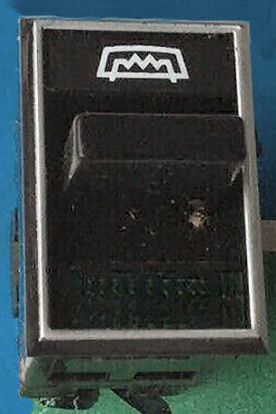
As I don't seem to have an 'electrics' page for the TVR yet, I'll just put a couple of bits of information on here... whilst working on the centre console (the alloy heater controls) I remembered that the backlighting on the console switches had been absent for some time. Purloined from (as I recall) the BL Princess, but also used on the Esprit and SD1, the Lucas switches have their logos lit by fibre-optics - well, this was the 1970s, remember ;o) Hidden behind the console is this spidery-looking thing:
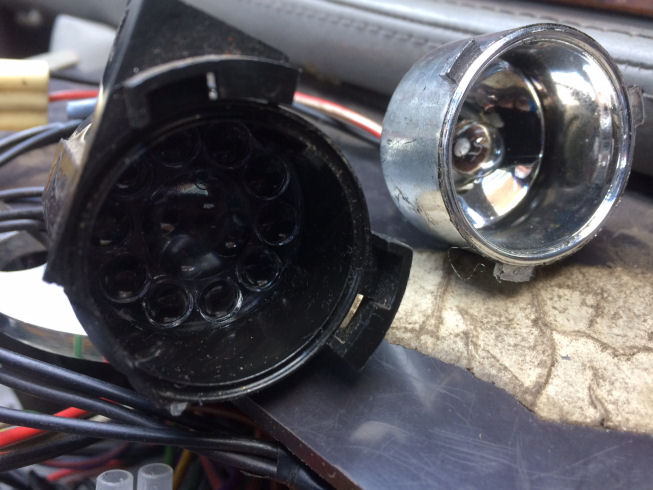
which, when you twist it open, reveals a small filament lamp and a number of lenses:
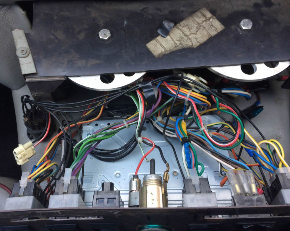
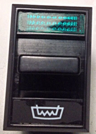
Behind each lens exits an optical fibre, the other end of which is plugged into a white plastic guide clipped to each switch. The guide serves to direct the light emitted by the fibre at the rear of the legend plate of the switch, supposedly letting you read its function. Hmm. Anyway, the bulb was blown; it's a Ba9 type with a small globe. However something creeping around in my memory tells me it was originally a larger globe that would have had its filament in a different place with repect to the various lenses (and possibly a higher rating than the 3.4W thing that was in there). I eventually managed to source from an Ebay seller a 5W bulb with the larger globe and the result is better but still feeble. I bought one of those Ba9-fitting LED clusters just to see if throwing more light around in the reflector would improve the situation but sadly not; bright as the LED appeared, it didn't backlight the switch logos as well as did the globe filament lamp. As a matter of interest here's an overview of what's hiding behind the centre console on the TVR wedges:
From left, mounted in the steel front plate: Window, Hazards, Blank, Cig lighter, Heater fan, Mirrors, Window. Below is the audio with (not visible) rear fog and front driving lamp switches to either side of it. Fibre-optic unit at rear left, heater dials at top of picture. By this point TVR were using sheet plastic fabrication for some parts as it was cheaper and quicker than GRP; the heater dials are bolted through the top of the folded-and-welded-plastic console structure which is not in a very good state at the moment... another job for another day. Note that wiring follows usual British colour convention.
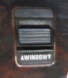
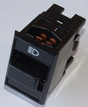
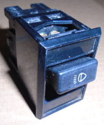
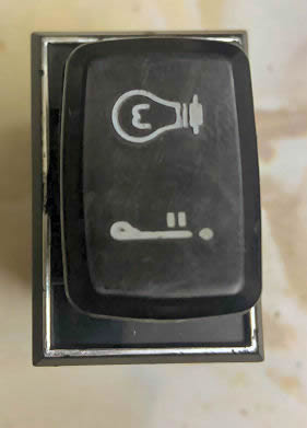
While we're on the subject of switches and as I don't seem to have a page for Wedge electrics as such, something to be aware of when sourcing replacement dash switches for the TVR is that Lucas made the same range of switches in a few different versions! Whilst they're all from the '182SA' series there are several variations in the style of the lever and the position of the legend. These switches were used on the TR7, BL Princess, Ambassador, some Reliant Scimitars, Lotus Esprit and others...
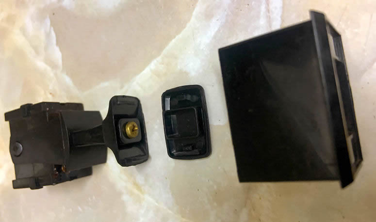
One style (the TVR variant, at left below) has the legend on a small plate that is glued-in either at the top or bottom of the housing depending on vehicle, and the end of the lever has a pattern of ribs (or grooves, depending on how you look at it). Next is the same legend plate with the end of the lever smooth, and thirdly is the smooth lever with the switch function labelled on the end of the lever, and then there's two versions with the very thin, plain lever, one of which had a silver trim line around it to make the Ambassador that bit less of a sow's ear ;o) Also shown is yet another variant with a large, bulbous end to the lever and the silver border; one version seems to have been based on the two-way centre-off (like an electric window switch) and functioned as an oil level check one way and a lamp test the other!
The 182SA series switches are easily disassembled and the brass contacts can be cleaned up if they've arced. They're not designed to handle large current drains, which didn't stop TVR trying to switch the high-speed winding of the heater fan motor through one, which almost melted the switch on my car. I repaired the damage and then fitted a relay that is energised by the switch in the high position. Incidentally, on the early Tasmin the heater fan only had one winding and thus only one speed; in order to create the 'low' setting TVR added several feet of wire, wound into a coil and hung off the back of the heater switch. This increased resistance slowed the motor down... which it didn't need, being so weedy in the first place. The later TVR Wedges got a proper multi-speed motor but its demist capabilities are still woeful. Something else to look into... one day ;)
Whilst dismantling the centre console to fit my modified switch, I realised that the clock had stopped! This is the second clock that car has had; the first died a few years ago, along with the Clifford alarm, after having had an Optimate charger connected to the car battery for some time. I didn't put two and two together at first, but I've since read that the Optimates have a desulphating function that works by superimposing high-voltage pulses or spikes onto the charge current. This apparently breaks down the build-up of sulphates on the lead plates which reduces the battery's function. Although the battery presents a massive 'sink' for the charge current, my guess is that the high-voltage spikes were too much for the microprocessor in the Clifford and the exceedingly rare L-131 chip that ran the clock (all other components measured OK, I just couldn't test the chip - and despite managing to 'scope the coded signal from the fob going into the Clifford's uPC, it refused point-blank to do anything). The Clifford was replaced with a later model and a forum member happened to have a spare clock which he let me have either free, or for not very much! Anyway, as I said it had stopped - and the car hasn't had an Optimate connected since the last episode, so I knew it wasn't a recurrence. Dismantling the 390SE's dashboard doesn't take long and I soon had the clock out (yes, I checked the fuse first!). I connected it to a bench PSU and could see that it was drawing a fluctuating current, between about 1 and 25mA, which was nice and regular... approximately 60 times a minute, in fact :D. This led me to think that the timing circuit was actually working, it just wan't moving the hands. On this variety of clock (a MotoMeter, although it could be a rebranded Kienzle) the hands are driven by a DC motor which is pulsed to give short bursts of rotation - not quite like a stepper motor, but similar. With the bezel carefully prised back to release the glass and three screws removed from the back, the mechanism dropped into my hand. The obvious suspects were a pair of 100uF 16V electrolytic capacitors. On the basis that the clock came from a car of about the same age as mine, the capacitors are 35 years old and known to fail. Sure enough, a multimeter on resistance range failed to elicit any charging indication from one of them, which was confirmed by a capacitance check using a different meter (my AVO M2005 is a similar era to the car and doesn't measure capacitance!). A quick rummage in the spares rack and seconds with a soldering iron had a replacement part fitted and the bench PSU had it ticking merrily away, now drawing a much more sensible 2-5mA . While I had the clock out I took the oppportunity to extract the backlight bulbs from the voltmeter and oil pressure gauge which have been blown for years! They're 12V 1.2W 'T5' types and have a green coating which gives that pleasing backlight colour. Of course I couldn't find any spares, but then it occurred to me that the fog and driving lamp switches on the centre console (which were accessible at the time) use the 'white' version of the same bulb. The green ones have a tiny green sort-of 'condom' fitted which can be carefully rolled-off in a post-coital fashion, so they were duly popped onto the still-functioning bulbs from the lights switches and refitted to the instruments, then the clock went back in and the dash looks like it's supposed to, once again. Ordered new lamps from an Ebay seller (in green and white, just in case!), which I'll put somewhere safe and forget I have them the next time one blows... meanwhile the 'new' switch was fitted in place of the centre console blank. For the life of me I can't find anyone selling the Lucas connector block which fits these 182SA-series switches. Luckily the terminals on the rear of the switch are the same size as the 3-way connector for the headlamp motors, of which I had a few spares, so I pinched the female terminals and pressed them onto the switch pins individually. I know, I could have bought a cheap electronic timer module and configured it to run the fuel pump for a few seconds whenever you turn the ignition on (which is what the later RV8 injection system did), but I quite like the idea of a manual switch, it adds to the 'fighter plane' feeling... ignition on, fuel rail at pressure, contact! Chocks away, tally-ho... \:^p
UPDATE 100424 - The clock is ticking!
The other day I was searching for some other thing when I rediscovered the first clock (see paragraph above) and immediately wondered if it might have the same issue. Stripped it down, hung my cheapo B&Q multimeter on (it has capacitance ranges, unlike my expensive old AVO) and it was immediately obvious that one of the caps had failed. Another dig in the spares boxes, 30 seconds with a soldering iron and it was ticking away as though it had never stopped! I left the clock connected to a bench PSU at about 14V for a day and the current fluctuated between about 2 and 8 milliamps (the high end being the pulses of the motor coil that moves the mechanism): it was still bang on time.
If you happen to be mad keen (or just mad) to pull your clock apart, be aware that it's just about impossible to put it back together afterwards without it being evident. Best you'll probably manage is to not leave any signs that are visible once the clock is back in the dash. With that caveat, begin by extracting the clock from the car! You'll need to unplug the backlight bulb, remove the 12V and ground feed wires, then undo the two knurled retaining nuts and slide off the retaining bracket: the clock should now fall out on your foot :D It'll be immediately obvious that the 'working parts' have to come out through the front of the casing, but the glass window is retained by a ring crimped all the way around. On some instruments this ring is brass and quite easy to work with: this one seems to be steel. You'll need a strong flat-blade screwdriver; insert the tip under the rear edge of the crimped ring and twist the driver. This will lift the ring away for a short length. Move the screwdriver round and repeat; continue like this, preferably only moving the metal a small amount at a time and using multiple passes until you'll eventually prise the ring edge up enough that it can be pulled off the instrument. This will allow the glass (actually plastic), with the adjustment knob, plus the internal trim ring to be extracted. Turning to the rear of the clock, there are 3 screws. Of of these connects a solder tag from the circuit board to the clock case, which is how the electronics are earthed. You could be a monkey and just bend the tag up once you've taken the screw out but it's far neater to desolder it. With that done and the three screws removed, the working parts can be slid out (or will have already fallen out on your foot :D). There's a rubber packing piece and insulating washer to lift off and then you can see the circuit board in all its glory. To extract the board there are 4 points where you'll need to desolder around pins; don't overdo it as the plastic frame underneath will melt from the heat you put into the pins. There aren't many components on the circuit board: the control IC, one resistor, a quartz crystal and the two electrolytics - plus the motor coil. You can check the winding for continuity, although I'm sure it'll be OK. If the IC has failed you're probably stuffed; quartz crystals don't often die but it wouldn't be unheard of. Chances are if anything's dies, it'll be one or both of the electrolytics.
Reverse the disassembly process to put it back together; to re-crimp the retaining ring I press the instrument down firmly on a hard surface with a suitable hole for the adjusting knob, then use a small hammer (couple of ounces) to work my way around, tapping the rim back into place. You'll never hide the marks caused by the screwdriver prising the rim outward but as said, as long as it looks OK from the front when back in the dash, you can't really expect much more.
UPDATE 181224
For as long as I've had the TVR, one of the things that has annoyed me is the gaping hole that the factory cut in the firewall in order to allow the speedo and bonnet release cables to pass through. It's something like 34mm diameter! I suspect just a case of whatever hole saw happened to be in the drill that day.
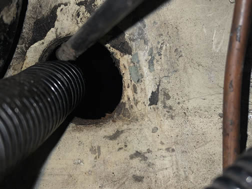
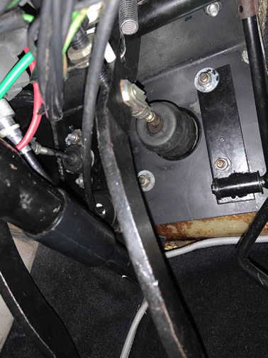
To be fair, I seem to think that the gearbox end of the Ford speedo cable had quite a large fitting, so maybe the cable was attached to the speedo first and then passed through from inside the cabin, and the spec was never changed for the smaller Rover cable end, but maybe I'm overthinking this... anyway, I decided it was time to do something about it... after 24 years. I gather that many cars just have a generous dollop of sealant clagged in there, and mine probably did as well until I had to pull the speedo cable out to have it copied for the cruise control installation. I thought there had to be a neater solution, and after trying to find a rubber grommet that could cope with 8mm of GRP plus the steel pedalbox without success, some sort of compression gland suggested itself. Now I guess if I'd looked hard enough I could have found some industrial fitting that would work, but a couple of issues presented themselves, not least of which was the angle that the bonnet release cable made on its way from the handle to the latch. Forcing it to detour through a gland of any length would put a hell of a kink in it. So I found an offcut of 50mm black acetal and got the measuring sticks out. The centre bore needed to be large enough for the speedo cable nut and the captive securing nut on the latch end of the bonnet cable. However, they didn't both need to pass through at the same time so the bore could be just large enough for the speedo nut. Unfortunately, the bonnet cable would need to be threaded through from the inside and the speedo cable from the outside! So I turned the main 'boss' with a flange in the engine bay and a thread in the cabin, with a matching nut (it's always fun making threaded components on the lathe). Some upside-down footwell gymnastics (not fun at my age) resulted, whereby the nut was passed over the bonnet cable and out through the boss, then the speedo cable could be passed through the boss and nut - to further complicate matters I cut a sheet rubber gasket to fit under the boss flange to stop fumes/vapour/ thunderstorms seeping past. The boss and gasket were then wedged into place in the hole while I grovelled inside to get the nut engaged on the thread and screwed up snugly. I knurled the nut to improve my grip on it as access for tools is restricted somewhat, as you'll know if you've ever wedged yourself under a Wedge dashboard. Unusually for me I didn't take any photos of the machining work, but here are a couple of the boss installed, first inside the cabin:
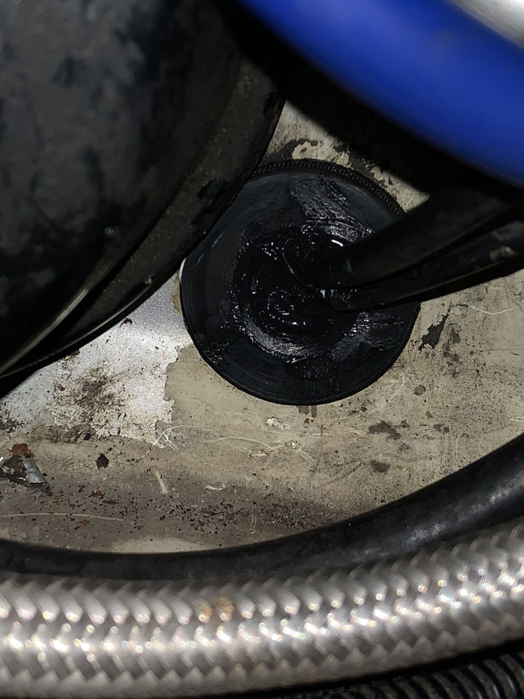
The bush is lower left of the pic, just above the steering column and left of the brake pedal - it's the bonnet release cable heading upwards. The speedo cable knurled nut to the cruise pulse generator is to the left of the red wire. In the photo below you can make out the rubber gasket behind the boss flange:
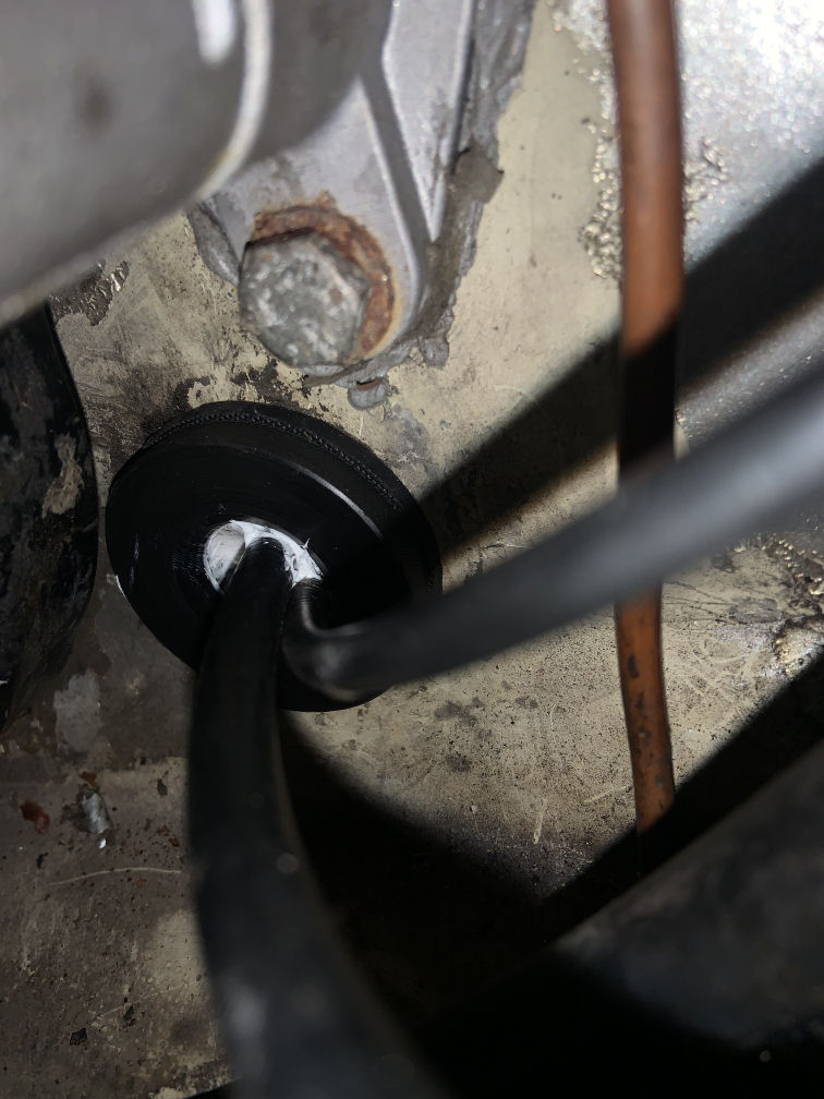
All I had to hand at the time was some white double-glazing Sikaflex sealant, which is good stuff but looked out of place so I found some Sikaflex 591i marine goo to top it up with :D
Another job done...